Configuration Screen
By default, the ezeio will connect to the cloud servers and synchronize data in both directions. This functionality is not optional, and normally requires no configuration. There are also a lot of other basic functions in the ezeio that always runs, such as scanning inputs, managing the power supply, keeping correct time etc.
The application functionality is controlled by the configuration system. This is similar to applications on a computer; the application controls if you are editing a spreadsheet or watching a movie, while the operating system runs in the background and provides the basics, like connecting to the Internet or taking input from the keyboard.
Similar to a computer, the ezeio functionality is dictated by Drivers. Drivers are in essence small programs that access resources (like inputs, outputs or communicates with a device via CAN or Modbus), and makes those resources available to the ezeio. In the ezeio, each driver allocates Registers (up to 150 per driver), and the registers are used in the ezeio to move data back-and-forth.
Data that needs to be recorded or sent to the servers must be mapped into Fields. Each ezeio can handle up to 90 (ninety) fields.
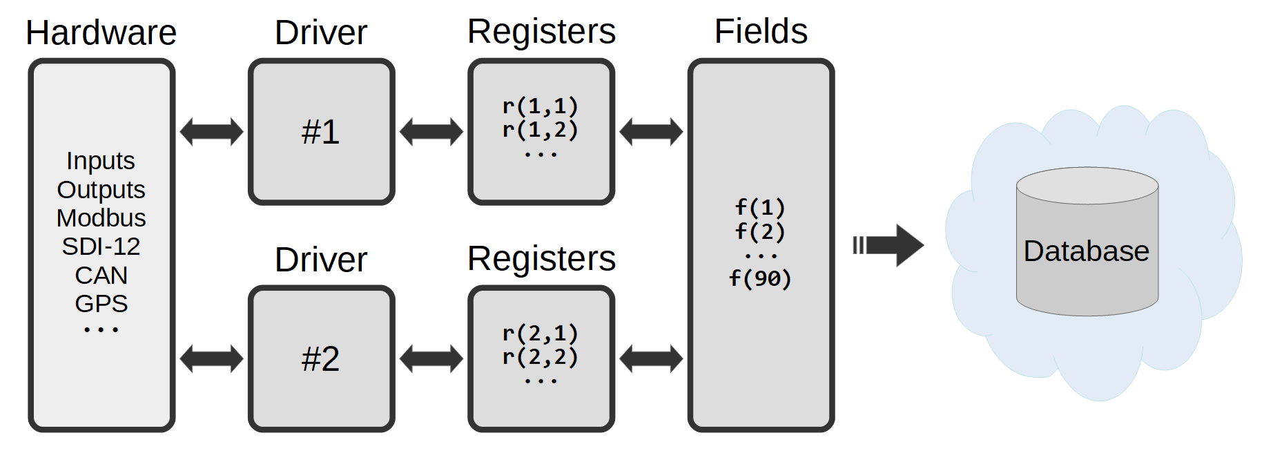
The ezeio can support up to 40 (forty) drivers at the same time, and each drivers typically works with a specific device or group of inputs/outputs. The resulting data is put into registers, where it can be easily referenced to by the fields.
The field data is automatically communicated to the servers.
Drivers are numbered 1 through 40. Usually each driver manages one device, such as a sensor or meter.
Registers are referenced by driver number and register number, so for example r(4,12) means it's the 12th register on device(driver) number 4.
Fields are simply referenced by their number; f(1) through f(90).
From LOGIN to, LOGGING DATA, in 4 easy steps
As shown in the graphic above, the typical process starts with connecting hardware (sensor/device). The Connecting Sensors and Peripherals section of this manual covers the basics of physically connecting peripherals to the ezeio. (The Device driver may contain device specific notes for comm port wiring). Once your device is connected, login to eze.ioand follow these steps.
From the “System” page;
- click the configure button for the desired ezeio
From the “Devices” page;
- Add a device driver, providing the programming to interpret the data or signal, allowing setting & preferences to be applied, and registers to be created on the ezeio. Save changes
- Select the registers you wish to add to Fields. Fields can be created and linked manually (see “Add Field” button)
From the “Fields” page;
- Configure the settings of each Field. Save changes
This simplified overview of the process is meant to serve as a generic guide. The process is the same for all external sources of data, whether that source is a simple sensor connected to one of the ezeio's input terminals or an engine control panel connect via Modbus (over a RS485 serial bus). The difference is in the specific settings within the “Device driver” and the amount of registers available from the device.
Configuration screen navigation
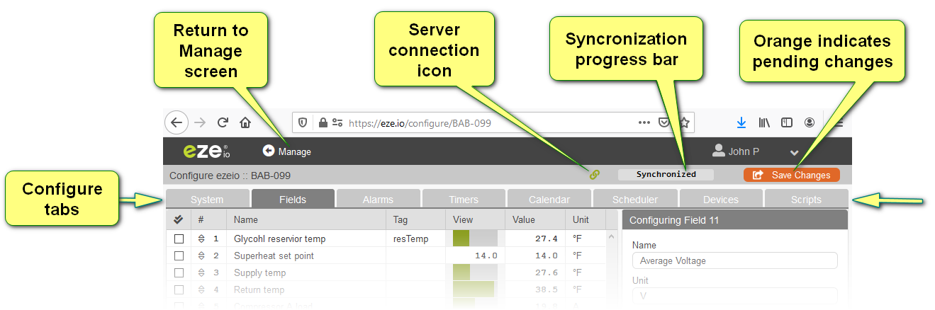
For users with full privileges, 8 tabs will be visible. Above these the banner contains (from left to right) the “Return to mange screen link” and the current users name. Clicking the user reveals the log out and view Terms of service options. Just below the banner, on the left, the serial number of the selected ezeio controller is displayed. To the right is the server connection icon, synchronization progress bar and save changes button.
Server connection icon
The ezeio controller connects periodically to the eze.io servers to send system and log data every 10 minutes (at a minimum). The server will also ping the ezeio at regular intervals. If all of these communications are normal, a green “linked ” symbol is displayed. If the server breaks the connection to the ezeio or the ezeio fails to respond to pings, an orange “broken link” symbol is displayed.
Synchronization progress bar
When saving changes, committing script edits or updating firmware, the progress bar will display the percentage of progress (graphically) in green as well as numerically. The delay in initiating these changes to the ezeio can vary from seconds to minutes. During this delay the progress bar will read “Update pending”. When no changes are pending the progress bar will read “Synchronized”.
Save changes button
Most changes made on the configuration level will cause the “Save changes button” to change from gray to orange with an animated symbol.