Power supply and power connections
The ezeio shall be powered from a DC (Direct Current) source, such as a AC/DC adapter, power supply or battery. Use only supplied or recommended power supplies with the ezeio.
Self draw
| Min | Max | Comment | |
|---|---|---|---|
| Input voltage | 11V 1) | 30V | DC |
| Current | 30mA 2) | 400mA 3) | 70mA average at 12V |
| Power | 50mW | 5W 4) | 0.8W average when using CAT-M1 |
Note; the above power consumption does not include any external connections.
The ezeio will start operating as soon as power is applied. There is no power switch. The ezeio is designed to stay powered at all times. There are no moving mechanical parts or anything that causes wear on the hardware. It generates very little heat. There is no need for ventilation.
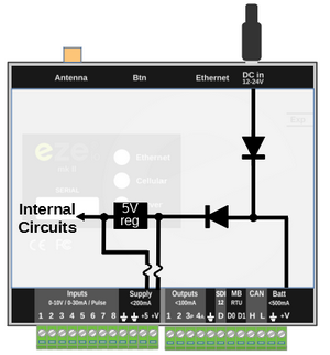
Feeding power to the ezeio - The power can be connected either via the DC Barrel jack on the top of the unit, or on the screw terminal. Do not supply power from more than one source at the same time.
Supplying power to sensors and peripherals - The terminals in the middle, marked 'Supply ,200 mA, +V' and +5 are designed to supply power to connected sensors and peripheral devices. If the ezeio is powered from the DC barrel jack, the screw terminals marked Batt, < 500 mA, '+V' can be used to route power to other devices as well. Please be careful to not overload the power supply. Do not load the 'Batt' output with more than 500mA. Do not load the 'Supply' terminal with more than 200mA.
Only the Supply +5 & +V terminals are protected with resettable fuses that will limit the output to about 200mA. There is no fuse on the Batt +V terminal. Overloading this terminal could damage the ezeio. If your sensors require more than 200 mA or you are unsure of their current draw, bypass the ezeio's circuitry and directly connect them to an adequate power supply.

All the terminals marked with a ground symbol are electrically connected together internally. This is also the same ground as the sleeve of the barrel jack, and the antenna connector.
Power connections on the green terminal
| Terminal | Max current | Purpose |
|---|---|---|
| Supply +5 | 200mA | Regulated 5V DC output for powering sensors/GPS that require a regulated 5V supply. |
| Supply +V | 200mA | Same voltage as the supply voltage. Fused with PTC. Intended to be used to power sensors that connects to the discrete inputs. |
| Batt +V | 500mA | Same voltage as the supply voltage. Not fused. May be used as either a power input 5) or output to power sensors and devices. Please make sure not to exceed 500mA. If higher current is required, use a separate power supply. |
Excitation current for passive sensors
When an input is configured for Resistive or Pulse mode, an internal switch will apply +5V through a 4870 Ohm resistor to the input terminal. There is usually no need for external excitation.
Outputs
The outputs emit the supplied DC voltage when turned on. Do not exceed 100mA on output 1-3. Do not exceed 20mA on output 4 (analog).