Pulse Input driver
Description
This driver (located in the Core drivers folder) is designed for use with the ezeio MkII controller and the ezeio MkII I/O Expander. Pulse outputs on common on meters for gas, water, and electrical. Most are designed to provide a volume total, such as liters or Kilowatt hours. The ezeio can also determine a flow rate based on the interval between pulses or the frequency (both methods can be employed by the driver to produce the most accurate flow value). This feature works best when the meter is ideally sized for the application, generating dozens of pulses per minute. The closer the pulse interval is to the logging interval the less accurate the flow data will be. Configuration settings allow conversion from the meters native unit to any of the most commonly used energy and flow/power units. One of the count registers (reg. #5) is writable (by default) via “Fields”, allowing privileged users to zero or change the pulse count. Changes to the count on register #5 will effect the scaled unit value on register #2.
Configuration Settings
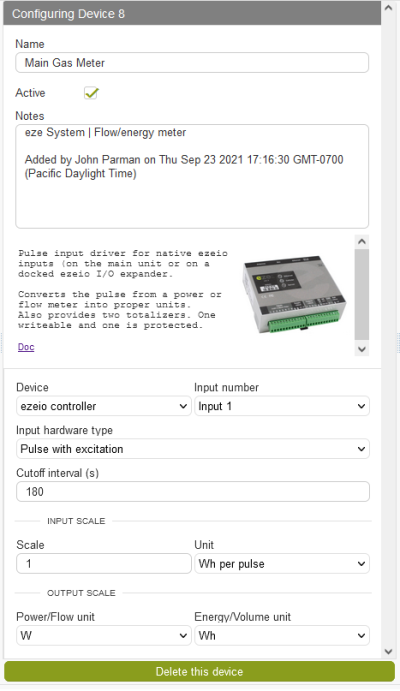
Name - The name is up to the user. Our suggestion is to choose a naming convention that makes the viewing the device list intuitive. Such as referring to the sensor and/or application. Keep the name short as it will be combined with the register name to create the default “Field” name (if added to “Fields”)
Notes - This space can be used to store information specific to the device, such as: location, wiring, scaling, etc.
Active Check box - Check this box and “Save changes” to run the driver. The driver program can be suspended by unchecking the box and clicking on “Save changes”.
Deactivating will cause the pulse count registers to reset to zero when the driver is reactivated
Device - Select the ezeio controller or the address number of a connected ezeio I/O Expander.
Input number - Select the input number (1-8) of the selected device.
Input hardware type - Select Pulse with or without excitation. Most applications use the default “Pulse with excitation” (ezeio provides 5 VDC pull-up). Check the manufactures documentation to if your meter to determine the correct setting.
Cutoff interval (s) - When calculating rate from a totalizers pulses, the value is continually calculated as it waits for the next pulse. If the flow stops, the driver will continue to reduce the rate value as it waits for the next pulse. To avoid force the driver to zero the rate, enter the number of seconds after witch the flow should be determined to have stopped. This interval will differ based on the characteristics of the meter and flow.
(Input) Scale Enter the rating value of the meter (one pulse = x units).
(Input) Unit - Select the rating unit of the meter (kW, L/min, gal/h, etc.)
(Output) Power/Flow unit - Select the desired unit for the rate to be shown in register #1. This allows the rate to be converted to a different unit type (such as BTU/s to Watts) or shown as the same rating given by the manufacture.
Registers
Reg #1 holds the scaled rate value, based on frequency of pulses and/or interval between pulses. The name and unit of this register will vary based on the “Power/Flow unit” selected by the user, in the driver configuration. Selecting kW will set the name as Power and selecting L/min will set the name as Flow.
Reg #2 holds the scaled accumulated value of register #5. The name and unit of this register will vary based on the “Energy/Volume unit” selected by the user, in the driver configuration. Selecting kWh will set the name as Energy and selecting L will set the name as Volume. The value can be reset to zero or user defined value by writing a new value to register #5 through “Fields”.
Reg #3 is identical to register #2, but is intended to hold a value that will not be reset. This value is based on the scaled accumulated value of register #6. The name and unit of this register will vary based on the “Energy/Volume unit” selected by the user, in the driver configuration. Selecting kWh will set the name as Energy and selecting L will set the name as Volume.
Reg #4 holds the frequency of the pulses. Unit is Hertz.
Reg #5 holds the resettable pulse count. Can be reset to a any value via “Fields” or “Script”. When added to “Fields” via the Device tab, the “Writable” option is checked by default.
Reg #6 holds the total pulse count. The intention is for this register to hold the lifetime pulse count. When added to “Fields” via the Device tab, the “Writable” option is unchecked by default.
