Outputs
The ezeio has four (4) outputs built in. Additional outputs can be added using ezeio expansion devices, or third party devices connected via Modbus, CAN or SDI-12.
ezeio MkII I/O expander - https://ezesys.com/ezeio-mkii-i/o-expander
The function of each output is completely controlled by software. The function can be programmed/automatic, manual or a combination of manual and automatic. Common use for outputs are to control a heating or cooling system based on the input from a temperature sensor (like a thermostat), controlling indicator lights or lighting, sprinkler control and much more.
The four outputs on the ezeio are of three types:
| Output number | Type | Range | Function |
|---|---|---|---|
| 1 and 2 | On/Off | 0-100 | Outputs 0V when off (<50) and supply voltage when on (>=50) |
| 3 | Pulse width | 0-100 | Outputs a 50Hz rectangular wave with duty cycle 0-100% |
| 4 | Analog | 0-100 | Outputs 0-10V based on its setting 0-100% |
Note; Output 3 can be used as a standard on/off output if set to 0/100%.
From the software, all outputs are controlled the same way, using a 0-100% setting.
Connecting loads to the outputs
The ezeio outputs are active, meaning they source a voltage when on. The voltage from output 1, 2 and 3 is sourced directly from the supply voltage, so if the ezeio runs on 15V, there will be 15V coming out from the outputs when they are switched on (100%).
The analog output will output 0-10V regardless of the supply voltage. If the supply voltage is less than about 11V, the analog output will not be able to support the full voltage range.
Do not connect external voltage to the outputs.
All outputs are fused with a self-resetting fuse. On output 1,2 and 3 the max continuous current output is 100mA. For the analog output, the max current output is 20mA.
Do not overload the outputs.
Any loads you connect to the outputs shall be connected between ground and the output only.
This shows a Solid State Relay connected to output #1 (note the polarity), and a standard relay connected to output #2:
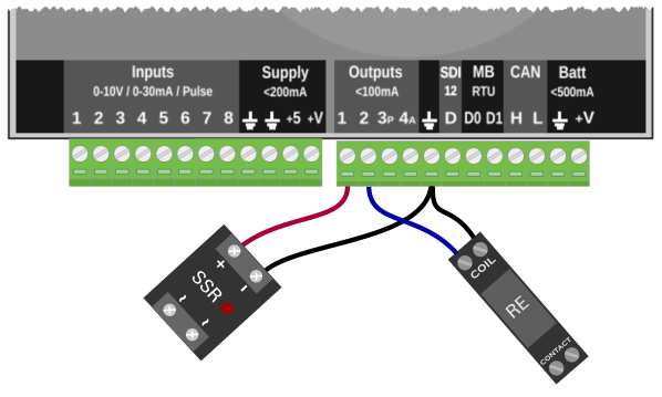
Digital outputs 1 and 2
Output 1 and 2 are digital, meaning they are either ON or OFF. When the output is OFF, there is no voltage on the terminal. When the output is ON, the voltage from the ezeio supply is routed to the output terminal.
Up to 100mA current can be continuously drawn from the output when it is ON. Each output is equipped with a self-resetting fuse. If the current exceeds 200mA, the fuse will open and stay open until the load is removed.
From the software, all outputs are controlled by setting the value between 0 and 100 (%). Any value 0-49 will set the digital outputs to OFF. Any value from 50-100 will set the digital outputs on ON. When reading the state of a digital output, the value will either be 0 or 100.
Digital/PWM output 3
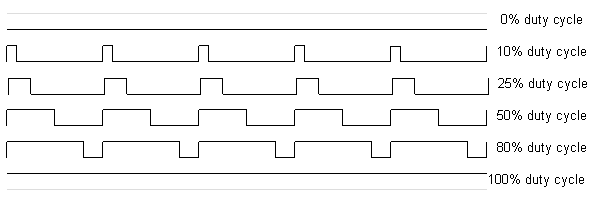
Output 3 is a PWM (Pulse Width Modulation) output. Cycle length is fixed at 50Hz. The percentage of time it stays “ON” (between 0% and 100%), during each cycle, is referred to as the “duty cycle” (see illustrated below). This type of output is typically used to vary speed or position, as part of a feedback loop. We recommend using the ezeio's “User script” and/or “Fields” to create the programming logic controlling the PWM output.
Just like the two digital outputs (1&2), the output voltage when in the ON state is the same as the supply voltage to the ezeio. The PWM output also uses the same type of fuse as output 1&2.
This output can be used as a 3rd digital output. When set to 0% or 100%, the PWM output behaves exactly like a standard digital output.
Analog output 4
Output 4 is an analog output. It will output a voltage between 0V and 10V. This is an advanced control/automation feature that requires programming through the ezeio's user script (see script examples below).
From software, the analog output can be set to any value between 0 and 100, where 0 = 0V output, and 100 = 10V output. So to get 7.5V output, set the value to 75.
The analog output can supply max 20mA output.
The analog output is a low current control signal output. It is not designed to drive loads directly.
The analog output range is fixed at 0-10V. It does not depend on the supply voltage to the ezeio.
For the analog output to work correctly, the supply voltage to the ezeio must be at least 11V. If the supply voltage is lower than 11V, the analog output will not be able to output the full range.
Script Examples
   Setoutput(4, 75); // Set a static level

   SetOutput(4, GetField(19));  // Use a "Field" to set level

// Use logic to increase level

   if( (T1-T2) > FanTempDelta )  // Compare feedback value
      SetOutput(4, GetOutput(4)+5);  // Increase speed