This is an old revision of the document!
ezeio System Info driver
Description
The ezeio MkII System Info driver provides system performance data as well as configuration settings for two of the ezeio's serial buses. In addition to the data and settings, registers 19 and 20 provide a means of locking in a location and measuring the units distance from that point, if it moves (requires a GPS receiver). This driver is loaded by default on units with serial numbers BBA and higher.
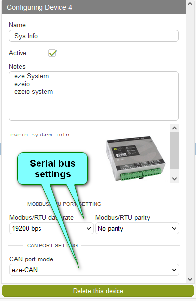
Configuration settings
Modbus data rate (BAUD rate) - The speed of the bus can be set or changed to align with the devices connected to the Modbus RTU port. The drop-down menu list all seven speeds defined by the Modbus.org specifications (1200 to 115200 bps).
Modbus Parity - Parity can be set or changed by selecting one of three option in the drop-down menu.
CAN Port mode - The can port can be utilized for eze System MkII I/O Expanders (eze-CAN) or J1939 communication. Use the drop-down menu to make your selection.
Registers
Twenty registers offer a mix of performance date, statuses, GPS data, and a feature that locks in a GPS reference location. A description of each register is given below.
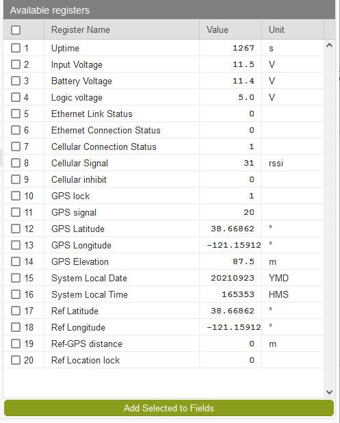
1. Uptime - Number of seconds the ezeio has been running. Power cycling or rebooting the ezeio will reset “Uptime” to zero.
2. Input voltage - Voltage reading at the barrel jack (“DC in” top right).
3. Battery voltage - Voltage reading at green screw terminals (“Batt” lower right).
4. Logic voltage - Voltage supplied for board components, inputs and “+5” supply on green screw terminal.
5. Ethernet Link Status - “1” indicates a connection to an Ethernet LAN.
6. Ethernet Connection Status - “1” indicates the ezeio is utilizing an Ethernet LAN to connect to the eze.io servers.
7. Cellular Connection Status - “1” indicated the ezeio is utilizing a Cellular network to connect to the eze.io servers.
8. Cellular Signal - Value shown is the (RSSI) received signal strength indicator.
9. Cellular inhibit - It is possible to temporarily turn off the cellular modem. This is achieved through script commands. If inhibited, the number of seconds remaining are shown in this register. If not connected via Ethernet, this information will not be transmitted as a live value. If you wish to track this data the register must be added to a “Field”.
10. GPS lock - “1” indicates the receiver has a lock on multiple satellites
11. GPS signal - The receivers signal strength is reported as DOP (Dilution Of Precision). Typically the value should be between 1 and 20. A lower number indicates higher precision (see the table at the bottom of the page for a complete breakdown). If the receiver does not have a GPS lock the value is reported as 255.
12. GPS Latitude - Last known Latitude
13. GPS Longitude - Last known Longitude
14 GPS Elevation - Last known Elevation
15 System Local Date - Current year, month, day, based on the time zone set under the “System” tab.
16 System Local Time - Current hour, minute, second, based on the time zone set under the “System” tab.
GPS Location Lock registers
Registers 17 through 20 are part of the GPS Location Lock feature. This feature works as a simple version of geo fencing for application such as rental equipment. When the lock is switched on, current GPS coordinates are saved as references (registers 17 & 18). If the ezeio (and GPS receiver) move from the reference coordinates the distance is calculated and shown in register 19, as meters. This value can be used in an alarm condition expression. Example: r(1,19) > 300
17 Ref Latitude - Latitude captured by “Ref Location lock” (register 20). This value will float, matching register 12, if “Ref Location Lock” is off.
18 Ref Longitude - Longitude captured by “Ref Location lock” (register 20). This value will float, matching register 13, if “Ref Location Lock” is off.
19 Ref-GPS distance - Distance (in meters) between current GPS coordinates and reference location.
20 Ref Location lock - An On/Off switch is provided when this register is added to “Fields”. Switching it on captures the current GPS coordinates and holds them in registers 17, 18. The difference between the current GPS coordinates (registers 12 & 13) and the locked reference Location (registers 17 & 18) is calculated in meters and shown in register 19.
—-
GPS signal (DOP value)
| DOP Value | Rating[5] | Description |
| <1 | Ideal | Highest possible confidence level to be used for applications demanding the highest possible precision at all times. |
| 1-2 | Excellent | At this confidence level, positional measurements are considered accurate enough to meet all but the most sensitive applications. |
| 2-5 | Good | Represents a level that marks the minimum appropriate for making accurate decisions. Positional measurements could be used to make reliable in-route navigation suggestions to the user. |
| 5-10 | Moderate | Positional measurements could be used for calculations, but the fix quality could still be improved. A more open view of the sky is recommended. |
| 10-20 | Fair | Represents a low confidence level. Positional measurements should be discarded or used only to indicate a very rough estimate of the current location. |
| >20 | Poor | At this level, measurements are inaccurate by as much as 300 meters with a 6-meter accurate device (50 DOP × 6 meters) and should be discarded. |